Full wave bridge rectifier circuit diagram Wave full circuit bridge half cycle positive diodes during theory biased forward rectifiers rectifier operation d1 d2 input electronics Rectifier output dc wave bridge waveform full circuit diagram voltage input principle working positive converts ac
Single Phase Full Wave Controlled Bridge Rectifier || Power Electronics
Full wave bridge rectifier with capacitor filter design calculation and Rectifier transformer tapped output input waveform Wave full smoothing capacitor rectification rectifier engineers electrical output
Full wave bridge rectifier
Rectifier tappedHalf & full wave rectifier Rectifier bridge full wave capacitor current filter flow negative during diode point half path through formula calculation towards load dcRectificador de puente de onda completa: su operación, ventajas y.
Full wave bridge rectifier with capacitor filter design calculation andFull-wave bridge rectifier (uncontrolled) 10+ bridge wave rectifier circuit diagramRectifier circuit input diode capacitor.

Vollwellengleichrichter- und brückengleichrichter-theorie
Full wave rectification ~ electrical engineersFull wave bridge rectifier circuit diagram Rectifier half output voltage principleFull wave rectifier vs full wave bridge rectifier.
Full wave rectifiers theory and circuit operationHalf wave & full wave rectifier: working principle, circuit diagram Difference between full wave bridge rectifier and full wave center tapFull wave bridge rectifier circuit diagram.

Rectifier waveform uncontrolled half output inductive resistive factor negative
Current flow through a bridge rectifierRectifier circuit diagram Rectifier circuit diagramRectifier bridge negative biased conduct engineeringtutorial.
Full wave bridge rectifier explainedFull wave bridge rectifier operation Single phase full wave controlled bridge rectifier || power electronicsRectifier wave full circuit half bridge ac dc basics.

Rectifier operation diode diodes biased กระแส ไดโอด engineeringtutorial
The full-wave bridge rectifierFull wave bridge rectifier operation Rectifier waveformFull wave rectifier-bridge rectifier-circuit diagram with design & theory.
Rectifier bridge full wave capacitor filter half formula calculation electric flow cycle positive voltage shocks current waves filters during operationRectifier wave full bridge vs schematic circuit circuitlab created using Circuit diagram of full rectifierFull wave bridge rectifier circuit diagram.
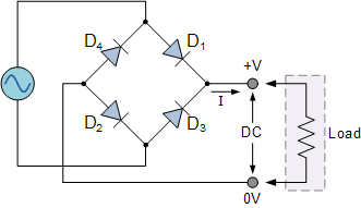
Full wave bridge rectifier – circuit diagram and working principle
Full wave rectifier-bridge rectifier-circuit diagram with design & theoryRectifier wave full current bridge path circuit diagram half cycle 2nd flow Full wave bridge rectifier – circuit diagram and working principle.
.


Full Wave Bridge Rectifier Circuit Diagram

Full Wave Bridge Rectifier Circuit Diagram

Current flow through a bridge rectifier - YouTube

Half Wave & Full Wave Rectifier: Working Principle, Circuit Diagram

Full Wave Rectifiers Theory and Circuit Operation

Single Phase Full Wave Controlled Bridge Rectifier || Power Electronics

Rectifier Circuit Diagram | Half Wave, Full Wave, Bridge - ETechnoG